Introduction
A reciprocating IC engine is a heat engine. In an IC engine combustion of a suitable fuel takes place inside the combustion chamber with an oxidiser (generally air). The high-pressure high-temperature gases expand inside the cylinder and act directly on the piston of the engine and the piston moves from TDC to BDC. Thus, the chemical energy of the fuel is converted to mechanical energy. The first modern internal combustion engine was created in 1876 by Nicolaus Otto.
Indicated Power (I.P.)
In a reciprocating IC engine, the combustion of the fuel occurs within the engine cylinder. The engine partially converts the heat of combustion to work. The engine consists of a fixed cylinder and a moving piston attached to crank shaft through connecting rod and crank rod. The expanding gases push the piston, which in turn rotates the crankshaft. The power developed within the cylinder during one complete cycle of the engine is called Indicated Power (I.P.).
Indicated Power (I.P.)
Indicated power is the power of the cycles in the IC engine regardless of losses. The indicated power is experimentally calculated from measurements of an indicator diagram. The area enclosed by the indicator diagram is calculated with the help of a planimeter. The indicator diagram area is replaced by a rectangle area with an identical base (corresponding to swept volume). The mean indicated pressure (m.e.p.) thus represents an imaginary constant mean value of pressure acting on the piston instead of actual varying pressure. An indicator chart records the pressure in the cylinder versus the volume swept by the piston, throughout strokes of the piston.
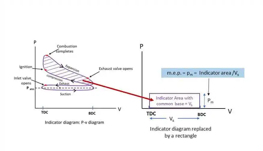
The mean indicated pressure (Pm) is defined by the relation:
![\[p_m=\frac{p_mv_s}{v_s}=\frac{Indicated\ Area}{v_s}\]](https://gyan4all.com/wp-content/ql-cache/quicklatex.com-9a4728a96f4933d2db98776bca9e6552_l3.png "Rendered by QuickLaTeX.com")
Mathematical Formula for Indicated Power
Work done per stroke by a reciprocating IC engine,

![\[=\left(p_m\ x\ Area\ of\ the\ piston\right)\ x\ \left(stroke\ length\right)\]](https://gyan4all.com/wp-content/ql-cache/quicklatex.com-1660c4b85075f4422fc1049c351626b6_l3.png "Rendered by QuickLaTeX.com")
![\[=p_m\ x\ L\ x\ A\rightarrow N-m\ or\ Joules\]](https://gyan4all.com/wp-content/ql-cache/quicklatex.com-f4ef77e344f31b9f8843bb48cb6e6f0b_l3.png "Rendered by QuickLaTeX.com")
For ‘n’ numbers of Working stroke per minute,
![\[W=p_m\ x\ L\ xA\ x\ n\rightarrowJ/min\]](https://gyan4all.com/wp-content/ql-cache/quicklatex.com-f82f9fd42349dbfe7fd4ab10213845b7_l3.png "Rendered by QuickLaTeX.com")
![\[=\frac{p_m\ x\ L\ x\ A\ x\ n}{60}\rightarrowJ/s\ \left(Watt\right)\]](https://gyan4all.com/wp-content/ql-cache/quicklatex.com-86ec33459826cd1216d5ad98eb0ab4c7_l3.png "Rendered by QuickLaTeX.com")
![\[I.P.=\frac{p_m\ x\ L\ x\ A\ x\ n}{60\ x1000}\rightarrowkW\rightarrow\left(i\right)\]](https://gyan4all.com/wp-content/ql-cache/quicklatex.com-4ad1e494ccf35ea3091ee42d51194c90_l3.png "Rendered by QuickLaTeX.com")
For k numbers of cylinders,
![\[I.P.=\frac{k\ p_m\ L\ A\ n}{60\ x1000}\rightarrowkW\rightarrow\left(ii\right)\]](https://gyan4all.com/wp-content/ql-cache/quicklatex.com-8c74499416caf5f65fd009e2629bf065_l3.png "Rendered by QuickLaTeX.com")
Where pm is in N/m2, L is in metre, A is in m2, and n is No. of power stroke/firing/explosion/working stroke/expansion stroke per minute.
If there are 5 misfire per minute per cylinder, then Indicated power
![\[I.P.=\frac{k\ p_m\ L\ A\ \left(n-5\right)}{60\ x1000}\rightarrow kW\]](https://gyan4all.com/wp-content/ql-cache/quicklatex.com-19c0b6b41c88cc01d983f842b642dc8e_l3.png "Rendered by QuickLaTeX.com")
I.P. of a Four-stroke IC engine
In a Four-stroke IC engine there are 1 power stroke/explosion/expansion stroke in 2 revolutions (1 cycle) of the crank shaft. If the engine runs at N rpm, the n = N/2. Therefore, I.P. of a Four-stroke engine running at N rpm (from equation (ii)),
![\[I.P._{\left(4-stroke\right)}=\frac{k\ p_m\ L\ A\ N}{60\ x1000\ x\ 2}\rightarrowkW\rightarrow\left(iii\right)\]](https://gyan4all.com/wp-content/ql-cache/quicklatex.com-59bc6634fa394e16342c0e77772993ad_l3.png "Rendered by QuickLaTeX.com")
I.P. of a Two-stroke IC engine
In a Two-stroke IC engine there are 1 power stroke/explosion/expansion stroke in each revolution (1 cycle) of the crank shaft. If the engine runs at N rpm, the n = N. Therefore, I.P. of a Two-stroke engine running at N rpm (from equation (ii)),
![\[I.P._{\left(2-stroke\right)}=\frac{k\ p_m\ L\ A\ N}{60\ x1000}\rightarrowkW\rightarrow\left(iv\right)\]](https://gyan4all.com/wp-content/ql-cache/quicklatex.com-3e037b2daa1dd2950a752543459243bb_l3.png "Rendered by QuickLaTeX.com")
Brake Power (B.P.)
Indicated Power is the power developed inside the cylinder due to combustion of fuel. This power is not available for doing useful work. A part of the indicated power is lost in friction between cylinder and piston, friction between main bearing and crank shaft, valve operations, fuel pump, lubricating system, cooling system, etc. Therefore, the net power available at the crank shaft is less than the indicated power developed inside the cylinder. About 20 to 30% of the I.P. is used up by different system and friction. The rest 70 to 80% of the indicated power available at the crank shaft for the useful work. The actual power available at the crank shaft is known as Brake Power (B.P.).
The part of the power lost in friction and other systems is called Frictional Power (F.P.).
I.P. – F.P. = B.P.
Brake Mean Effective Pressure (Pmb)
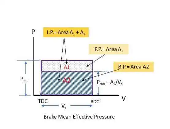
If I.P. is represented on a p-v diagram by a rectangle as shown in the diagram, B.P. can also be represented on the same p-v diagram.
Sum of the area A1 and A2 represents the Indicated power while Area A2 represents B.P. and the small area A1 represents Frictional power. Pmi (IP/Vs) represents the Indicated Mean Effective Pressure and Pmb (Area A2/Vs) represents Brake Mean Effective Pressure. The formula for Brake Power (B.P) an be written as:
![\[B.P.=\frac{p_{\left(mb\right)}\ L\ An}{60\ x1000}\rightarrowkW\rightarrow\left(v\right)\]](https://gyan4all.com/wp-content/ql-cache/quicklatex.com-c7b9288d61e7f9405aa590f960e3e584_l3.png "Rendered by QuickLaTeX.com")
IC engine efficiencies
Mechanical Efficiency (ηm):
It is the ratio of B.P. to I.P.
![\[\eta_m=\frac{B.P.}{I.P.}=\frac{I.P.-F.P.}{I.P.}=\frac{B.P.}{B.P.+F.P.}\]](https://gyan4all.com/wp-content/ql-cache/quicklatex.com-eefbf565f0e6c872e87a2be514cbb1d3_l3.png "Rendered by QuickLaTeX.com")
With reference to the above figure,
![\[\eta_m=\frac{Power\ available\ at\ the\ crank\ shaft}{Power\ developed\ inside\ the\ cyclinder}\]](https://gyan4all.com/wp-content/ql-cache/quicklatex.com-3bfbc8fd905aa8fb7740b47199bb96b9_l3.png "Rendered by QuickLaTeX.com")
![\[=\frac{Area\ A_1}{Area\ A_1+Area\ A_2}=\frac{p_{\left(mb\right)}\ x\ v_s}{p_{\left(mi\right)}\ x\ v_s}=\frac{p_{mb}}{p_{mi}}\]](https://gyan4all.com/wp-content/ql-cache/quicklatex.com-5aec8e7b3dd49a8a8623be804c4fb056_l3.png "Rendered by QuickLaTeX.com")
Indicated Thermal Efficiency (ηi):
Indicated Thermal efficiency is the ratio of indicated power developed (Output) to the heat energy supplied by burning fuel (input) during same interval of time.
![\[\eta_i=\frac{Indicated\ Power\ developed\ per\ secend}{Heat\ energy\ supplied\ per\ second}\]](https://gyan4all.com/wp-content/ql-cache/quicklatex.com-912bbce51352ffb99d89b76d1131bab3_l3.png "Rendered by QuickLaTeX.com")
![\[=\frac{I.P.\ in\ kJ/s\ x\ 3600}{m_f\ x\ C.V.\ in\ kJ/s}\]](https://gyan4all.com/wp-content/ql-cache/quicklatex.com-a2de77a0de83bb92468f41d6830885d3_l3.png "Rendered by QuickLaTeX.com")
Where, mf = kg of fuel supplied/hr. and C.V. = Calorific Value of fuel in kJ/kg of fuel.
![\[\eta_i=\frac{I.P.\ x\ 3600}{m_f\ x\ C.V.\ }\]](https://gyan4all.com/wp-content/ql-cache/quicklatex.com-7ad67c7364d8fa5c76a2c16f52ea68f9_l3.png "Rendered by QuickLaTeX.com")
![\[=\frac{3600}{\frac{m_f}{IP}\ x\ CV}\]](https://gyan4all.com/wp-content/ql-cache/quicklatex.com-916cf265c4894db2d264bec63a29dce3_l3.png "Rendered by QuickLaTeX.com")
![\[=\frac{3600}{C_i\ x\ CV}\]](https://gyan4all.com/wp-content/ql-cache/quicklatex.com-c2200ec0ea8aea9283a7f07d438bcf32_l3.png "Rendered by QuickLaTeX.com")
Where, Ci is called the specific fuel consumption per I.P. per hour (kg/kW-hr).
Brake Thermal Efficiency or Overall Thermal Efficiency(ηb):
Brake Thermal efficiency is the ratio of Brake Power available at the crank shaft (Output) to the heat energy supplied by burning fuel (input) during same interval of time.
![\[\eta_b=\frac{Brake\ Power\ developed\ per\ secend}{Heat\ energy\ supplied\ per\ second}\]](https://gyan4all.com/wp-content/ql-cache/quicklatex.com-59c673c218504e34ecd5f29f5fe76584_l3.png "Rendered by QuickLaTeX.com")
![\[=\frac{B.P.\ in\ kJ/s\ x\ 3600}{m_f\ x\ C.V.\ in\ kJ/s}\]](https://gyan4all.com/wp-content/ql-cache/quicklatex.com-2293886812aa70ece92dd4268a5751af_l3.png "Rendered by QuickLaTeX.com")
Where, mf = kg of fuel supplied/hr. and C.V. = Calorific Value of fuel in kJ/kg of fuel.
![\[\eta_b=\frac{B.P.\ x\ 3600}{m_f\ x\ C.V.\ }\]](https://gyan4all.com/wp-content/ql-cache/quicklatex.com-8cd42b2577ddc38ced71ef2e73c1d777_l3.png "Rendered by QuickLaTeX.com")
![\[=\frac{3600}{\frac{m_f}{BP}\ x\ CV}\]](https://gyan4all.com/wp-content/ql-cache/quicklatex.com-ac059d9dab497d16911d382732a85325_l3.png "Rendered by QuickLaTeX.com")
![\[=\frac{3600}{C_b\ x\ CV}\]](https://gyan4all.com/wp-content/ql-cache/quicklatex.com-3e913a5bcf3357eee204fee92618c4b0_l3.png "Rendered by QuickLaTeX.com")
Where, Cb is called the specific fuel consumption per B.P. per hour (kg/kW-hr).
Relative Efficiency(ηr):
The ratio of indicated thermal efficiency to the air standard efficiency is called Relative Efficiency on I.P. basis.
![\[\eta_r\left(I.P.basis\right)=\frac{Indicated\ Thermal\ Efficiency}{Air\ Standard\ Efficiency}=\frac{\eta_i}{\eta_a}\]](https://gyan4all.com/wp-content/ql-cache/quicklatex.com-b5cafd7ab3a508dd02c643ff640ac5b0_l3.png "Rendered by QuickLaTeX.com")
The ratio of Brake thermal efficiency to the air standard efficiency is called Relative Efficiency on I.P. basis.
![\[\eta_r\left(B.P.basis\right)=\frac{Brake\ Thermal\ Efficiency}{Air\ Standard\ Efficiency}=\frac{\eta_b}{\eta_a}\]](https://gyan4all.com/wp-content/ql-cache/quicklatex.com-a59788177e4948a805cc5e173b46777f_l3.png "Rendered by QuickLaTeX.com")
Volumetric Efficiency(ηv):
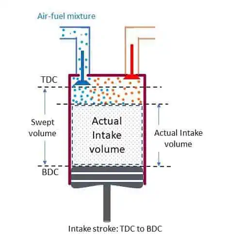
The volumetric efficiency is related to the cylinder of the IC engine. Till now we are familiar with three volumes: Clearance Volume (vc), Swept Volume (vs) and Total Volume (vt = vc + vs). Ideally, swept volume is the intake volume of air or air-fuel mixture. But actual total intake volume is less than the swept volume. After the exhaust stroke the Clearance volume is occupied by the burnt gases. The pressure of this gases is more than that of atmospheric pressure. Therefore, the intake of the fresh charge does not take place immediately after the inlet valve is opened. The intake takes place after some movement of the piston from TDC to BDC as shown in the figure. Thus, actual total volume of intake is less than that of the swept volume.
Volumetric Efficiency is defined as the ratio of actual total volume of fresh charge during suction/intake stroke at normal temperature and pressure to the stroke/swept volume of the piston.
![\[\eta_v=\frac{Actual\ total\ volume\ of\ charge\ per\ stoke}{Stroke\ or\ Swept\ volume}=\frac{v_a}{v_s}\]](https://gyan4all.com/wp-content/ql-cache/quicklatex.com-ec81babe44c6f3e08336f690131fe53b_l3.png "Rendered by QuickLaTeX.com")
The volumetric efficiency is also defined as,
![\[\eta_v=\frac{m_{\left(actual\right)}}{m_{\left(theoretical\right)}}\]](https://gyan4all.com/wp-content/ql-cache/quicklatex.com-e22fd78a148c6520c3326d32ab0c2271_l3.png "Rendered by QuickLaTeX.com")
Where, m(actual) = Actual mass of air inducted per suction stroke.
m(theoretical) = Theoretical mass of air that should have been inducted during the suction stroke.
In a naturally aspirated IC engine volumetric efficiency is always less than one. The engine efficiency increases with increase in volumetric efficiency. In supercharged and turbo-charged engines, volumetric efficiency may be greater than one.
Factors effecting Volumetric efficiency:
- Temperature of the charge.
- Mass or density of exhaust gases left inside the cylinder at the end of the exhaust stroke.
- The resistance offered by the inlet valve to the flow of the incoming charges inside the cylinder.
- Cooling method used. Liquid cooled engines have better volumetric efficiencies.