Thermodynamic Cycle
A heat engine is a combination of processes completing one cycle. Reversible cycles are the most efficient cycles and they give maximum efficiencies. But, reversible cycles are ideal cycles only so they cannot be achieved in practice.
Gas power cycles are cycles of those heat engines in which the working fluids remain in a gaseous state throughout the cycle. The performance of a heat engine is measured in terms of thermal efficiency (ηth). Cycle efficiency is the ratio of network output (Wnet) divided by Heat supplied (Qs).
![\[\eta_{th} = \frac{W_{net}}{Q_s}\]](https://gyan4all.com/wp-content/ql-cache/quicklatex.com-2a43b97b88ad29b794be603bd8d28c33_l3.png "Rendered by QuickLaTeX.com")
The efficiency of an engine using air as the working medium is called Air standard efficiency(ηair). Actual Gas power cycles are very complex for analysis. Analysis of gas power cycles are made simpler by approximation to air standard cycle with some assumptions.
Assumptions of Air standard Cycles
- In Gas power cycles, the air is assumed to be the working fluid.
- Air is an ideal gas, and it recycles in a closed cycle.
- All processes of the cycle are internally reversible.
- Heat addition is done from an external source of infinite heat at a higher temperature.
- Heat rejection is done to an external Sink at a lower temperature.
- Specific heat of air remains constant at all temperatures.
Otto Cycle: Ideal cycle for Spark Ignition Engine
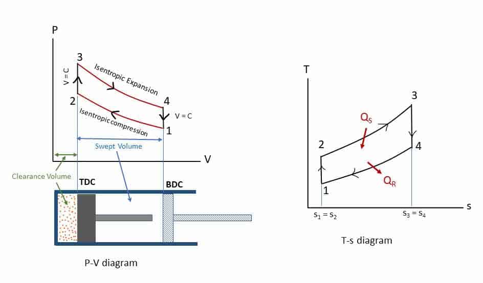
Otto cycle is the idealized thermodynamic cycle which describes the working of a typical spark-ignition petrol or gas engine. Nikolaus Otto invented it in 1867. All air-standard assumptions are applicable in ideal Otto cycles. The Otto cycle consists of four reversible processes: compression, heat addition, expansion, and heat rejection. The figures below describe the theoretical processes by p-v diagram and T-s diagrams of this cycle respectively.
- Process 1-2: Isentropic (reversible adiabatic: s1 = s2) compression from volume v1 to v2 and pressure p1 to p2.
- Process 2-3: Constant volume heat addition (Qs) process (V2 = V3).
- Process 3-4: Isentropic expansion (s3 = s4) expansion from volume v3 = v2 to v4 = v1 and pressure p3 to p4.
- Process 4-1: Constant volume heat rejection (Qr) process(V4 = V1).
Efficiency of Otto cycle
Considering m kg of working fluid (air),
Heat supplied Qs = m cv (T3 -T2) kJ
Heat rejected Qr = m cv (T4 -T1) kJ
Net work done, Wnet = Qs – Qr
Air standard efficiency,
![\[\eta_{otto} =\eta_{th}= \frac{W_{net}}{Q_s}\]](https://gyan4all.com/wp-content/ql-cache/quicklatex.com-4ad25f4384c8d94057967789252357fb_l3.png "Rendered by QuickLaTeX.com")
![\[=1- \frac{Q_{r}}{Q_s}\]](https://gyan4all.com/wp-content/ql-cache/quicklatex.com-455a0f6079f3219562ca9f8fd4d077e1_l3.png "Rendered by QuickLaTeX.com")
![\[=1- \frac{mc_{v}{(T_4-T_1)}}{mc_{v}{(T_3-T_2)}}\]](https://gyan4all.com/wp-content/ql-cache/quicklatex.com-651cf61f5a467aa2bfcf89ad800672fc_l3.png "Rendered by QuickLaTeX.com")
![\[=1- \frac{(T_4-T_1)}{(T_3-T_2)} \rightarrow (i)\]](https://gyan4all.com/wp-content/ql-cache/quicklatex.com-b32f15d707033bada38eab7abb9b41e5_l3.png "Rendered by QuickLaTeX.com")
Applying Isentropic Law to the process 1-2,
![\[\frac{T_2}{T_1}= \left(\frac{{v_1}}{{v_2}}\right)^{\gamma-1} = {r_c}^{\gamma-1}\]](https://gyan4all.com/wp-content/ql-cache/quicklatex.com-c8baff9b81283c97fac6af7710d61ac6_l3.png "Rendered by QuickLaTeX.com")
Therefore,
![\[T_2= T_1{r_c}^{\gamma-1} \rightarrow (ii)\]](https://gyan4all.com/wp-content/ql-cache/quicklatex.com-a8d1ada23f92b3949204197288f51c2c_l3.png "Rendered by QuickLaTeX.com")
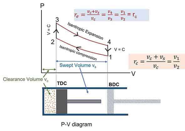
Where, rc = Compression ratio
![\[= \frac {v_1}{v_2}\]](https://gyan4all.com/wp-content/ql-cache/quicklatex.com-b25983c4072a08aaa05b47feab337f2e_l3.png "Rendered by QuickLaTeX.com")
Similarly, applying Isentropic Law to the process 3-4,
![\[\frac{T_3}{T_4}= \left(\frac{{v_3}}{{v_4}}\right)^{\gamma-1} = {r_e}^{\gamma-1}\]](https://gyan4all.com/wp-content/ql-cache/quicklatex.com-3073f324e3b0a579e3b2199aafb21d9d_l3.png "Rendered by QuickLaTeX.com")
![\[\frac{T_3}{T_4}= {r_c}^{\gamma-1}, \longleftrightarrow since: r_c = r_e\]](https://gyan4all.com/wp-content/ql-cache/quicklatex.com-885ba579b65b4ed22a9f7df5116d0c40_l3.png "Rendered by QuickLaTeX.com")
Putting the value of T2 and T3 in equation (i),
![\[\eta_{otto} =\eta_{th}= 1- \frac{{1}}{{r_c}^{\gamma-1}}\]](https://gyan4all.com/wp-content/ql-cache/quicklatex.com-876ca3a58e92c668bb1dfa9b3e2d4416_l3.png "Rendered by QuickLaTeX.com")
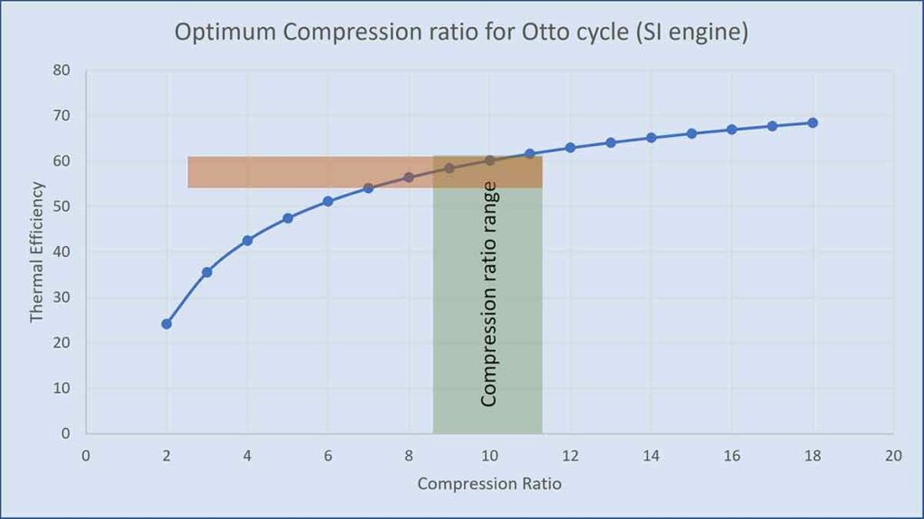
Thus, efficiency is a function of compression ratio only  = 1.4 for air). Putting different values of rc , the efficiencies are tabulated below.
| rc | 2 | 3 | 4 | 5 | 6 | 7 | 8 | 9 | 10 | 11 | 12 | 13 | 14 |
 | 24.2 | 35.6 | 42.6 | 47.5 | 51.2 | 54.1 | 56.5 | 58.5 | 60.2 | 61.7 | 63.0 | 64.2 | 65.2 |
From the table and the graph, you can understand that efficiency increases with an increase in compression ratio. But there is a limitation on compression ratio for petrol engine (SI engine). If the compression ratio increases, temperature increases, and at high temperature there would be pre-ignition of the fuel before the spark. The pre-combustion of the air-fuel mixture in the cylinder is called knocking characterized by a sharp sound. The graph shows a typical range of compression ratio for gasoline engines (7:1 to 10:1) which gives a theoretical efficiency in the range of about 54% to 60 %. Modern engines use a range of compression ratios from 8 to 11 giving an ideal cycle efficiency of 56% to 61%.
Four Stroke Spark Ignition Engine
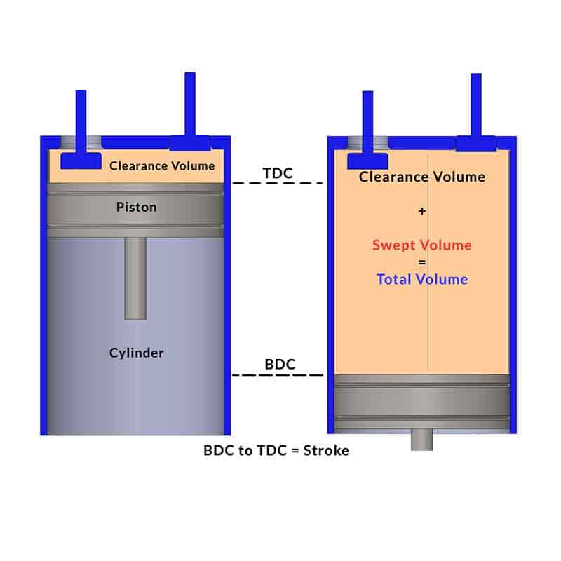
We have understood the ideal Air standard Otto cycle which approximates the Spark Ignition gasoline engine. Now we will discuss the actual four-stroke petrol engine with intake or suction of air-fuel mixture, actual combustion process, expansion or working stroke, and actual exhaust of gases from the cylinder. Four-stroke spark-ignition engines consist of piston-cylinder arrangements with intake and exhaust valves. There are four strokes of the piston within BDC (Bottom Dead Centre)) and TDC (Top Dead Centre).
Suction or Intake Stroke
The Piston moves from TDC to BDC while the Inlet valve remains open. So, the Air-fuel mixture enters the cylinder due to slight vacuum pressure created inside the cylinder. Thus, Suction or intake continues till the piston reaches the BDC.
Compression Stroke
Both the valves remain closed, and the piston moves from BDC to TDC. The air-fuel mixture is compressed and the temperature and pressure increase. Toward the end of the stroke, the Spark plug creates the spark, and the combustion of the fuel begins at constant volume. The combustion process is equivalent to the Constant volume heat addition in the Air standard Otto Cycle.
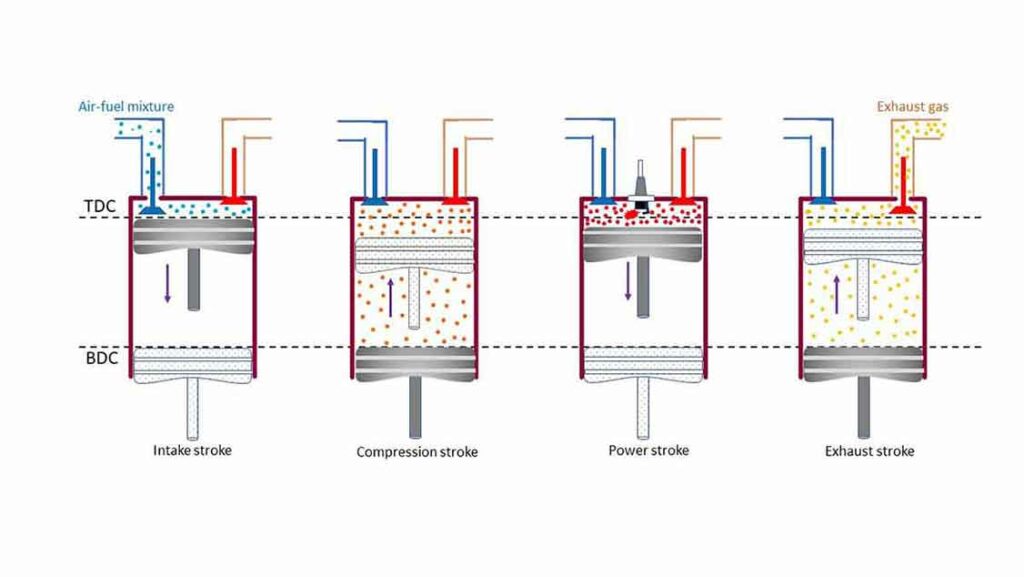
Expansion or Power or Working Stroke
After the completion of the combustion, the high-pressure gas pushes the piston from TDC to BDC (Power or Work). During this stroke, work is done by the cycle and the stroke is also known as working or power stroke.
Exhaust Stroke
In this stroke, the piston moves from BDC to TDC while the Exhaust valve remains open. The product of combustion is forced out of the cylinder at a pressure slightly higher than the atmospheric pressure. This process is equivalent to the heat rejection in the Otto cycle.
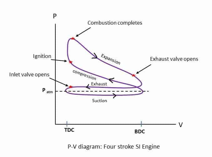
Four strokes and the combustion process of the Petrol engine are represented by the P_V diagram as shown in the diagram below. The actual p-v diagram is different from the theoretical one because the events of valve opening and closing as well as ignition etc. are not instantaneous and sharp.
Diesel Cycle: Diesel Combustion Engine cycle
The Diesel cycle is the idealized thermodynamic cycle that describes the working of a typical diesel combustion compression ignition engine. This cycle was introduced by Dr. R. Diesel in 1897. The only difference with the Otto cycle is that the heat addition takes place at constant pressure. This is also known as the constant-pressure heat addition cycle. All air-standard assumptions are applicable in ideal Diesel cycles. The Diesel cycle consists of four reversible processes: compression, heat addition, expansion, and heat rejection. The figures below describe the theoretical processes by p-v diagram and T-s diagrams of this cycle.
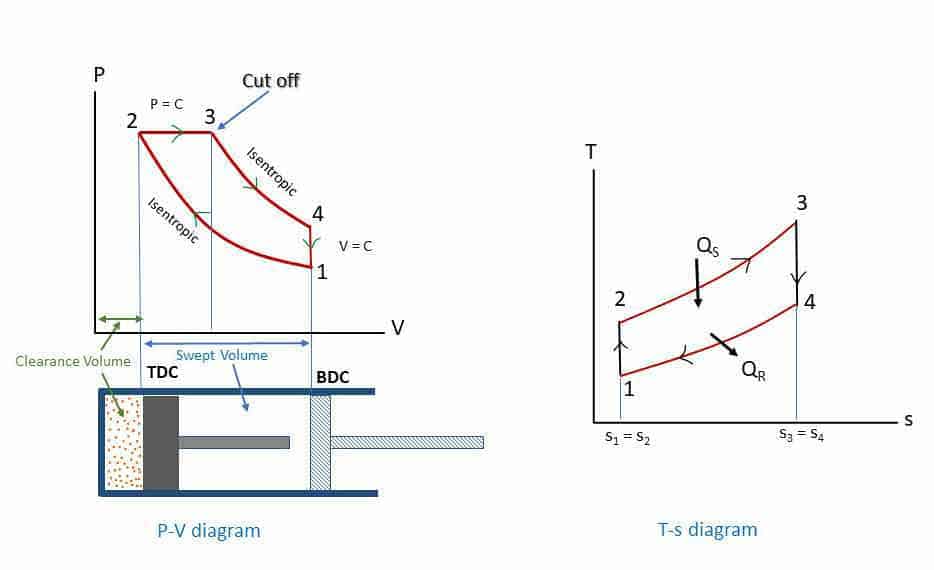
- Process 1-2: Isentropic (reversible adiabatic: s1 = s2) compression from volume v1 to v2 and pressure p1 to p2.
- Process 2-3: Constant pressure heat addition (Qs) process (P2 = P3).
- Process 3-4: Isentropic expansion (s3 = s4) expansion from volume v3 to v4 = v1 and pressure p3 to p4.
- Process 4-1: Constant volume heat rejection (Qr) process (v4 = v1).
Thermal efficiency: Diesel cycle/engine (Gas Power cycle)
Considering m kg of working fluid (air),
Heat Supplied, Qs = m cp (T3 – T2) kJ [constant pressure heat addition process]
Heat rejected Qr = m cv (T4 -T1) kJ [constant volume heat rejection process]
Air standard efficiency,
![\[\eta_{diesel} =\eta_{th}= \frac{W_{net}}{Q_s}\]](https://gyan4all.com/wp-content/ql-cache/quicklatex.com-275ffc81b668b88674eea767d4706032_l3.png "Rendered by QuickLaTeX.com")
Net work done, Wnet = Qs – Qr
![\[\eta_{th} = \eta_{diesel} =1- \frac{Q_{r}}{Q_s}\]](https://gyan4all.com/wp-content/ql-cache/quicklatex.com-234a0f66b243451c8a7c45cd148d3b84_l3.png "Rendered by QuickLaTeX.com")
![\[=1- \frac{mc_{v}{(T_4-T_1)}}{mc_{p}{(T_3-T_2)}}\]](https://gyan4all.com/wp-content/ql-cache/quicklatex.com-07e3216cb024e3372a2c36146ccdb200_l3.png "Rendered by QuickLaTeX.com")
![\[=1- \frac{(T_4-T_1)}{\gamma(T_3-T_2)} \rightarrow (i)\]](https://gyan4all.com/wp-content/ql-cache/quicklatex.com-abfc23a53e8f89e65c45a05d8cee56ed_l3.png "Rendered by QuickLaTeX.com")
![\[where, \gamma = \frac{c_p}{c_v}\]](https://gyan4all.com/wp-content/ql-cache/quicklatex.com-494a18f4b44048fe16656016c13f418b_l3.png "Rendered by QuickLaTeX.com")
Applying Isentropic Law to the process 1-2,
Therefore,
Again, applying Isentropic Law to the process 3-4,
Therefore,
![\[T_3= T_4{r_e}^{\gamma-1} \rightarrow (iii)\]](https://gyan4all.com/wp-content/ql-cache/quicklatex.com-7255f07c980671262b08be3ad3e0e494_l3.png "Rendered by QuickLaTeX.com")
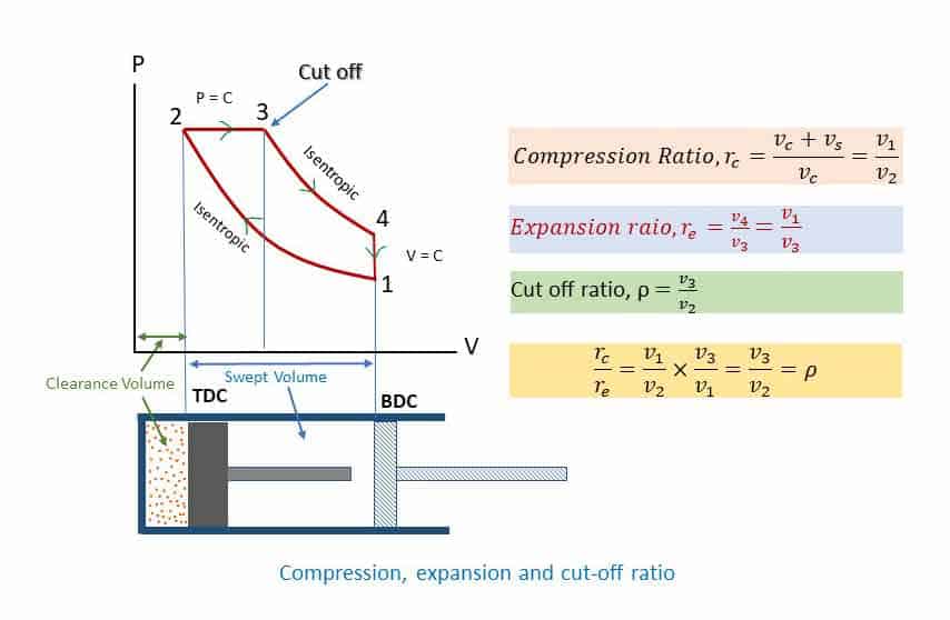
Again, Cut-off ratio,
![\[\rho =\frac{v_3}{v_2}=\frac{r_c}{r_e} \]](https://gyan4all.com/wp-content/ql-cache/quicklatex.com-714844aa7611643996a6851ee5fd2868_l3.png "Rendered by QuickLaTeX.com")
(See the p-v diagram for compression, expansion, and cut-off ratio)
(Cut off is the point at which the heat addition is stopped – point 3 in the p-v diagram. Heat addition starts at point 2)
Putting the value of T2 and T3 in equation (i), and, simplifying
ηth = ηDiesel
![\[=1- \frac{(\rho^\gamma-1)}{({\gamma}) r_c^{\gamma-1}(\rho-1)} \rightarrow (iv)\]](https://gyan4all.com/wp-content/ql-cache/quicklatex.com-fb019bc14329e4068f7a7aee663cc06c_l3.png "Rendered by QuickLaTeX.com")
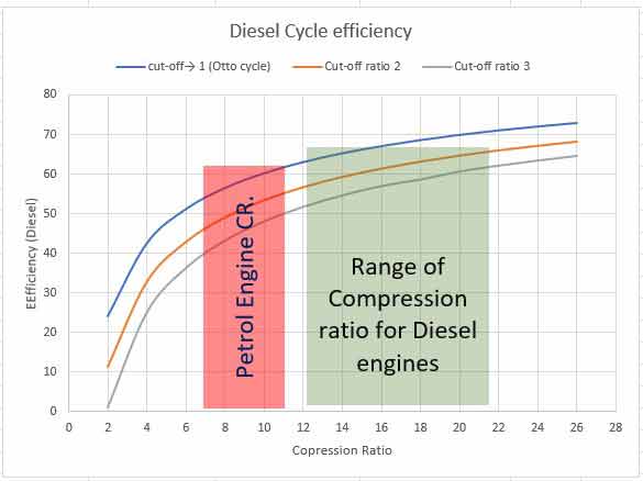
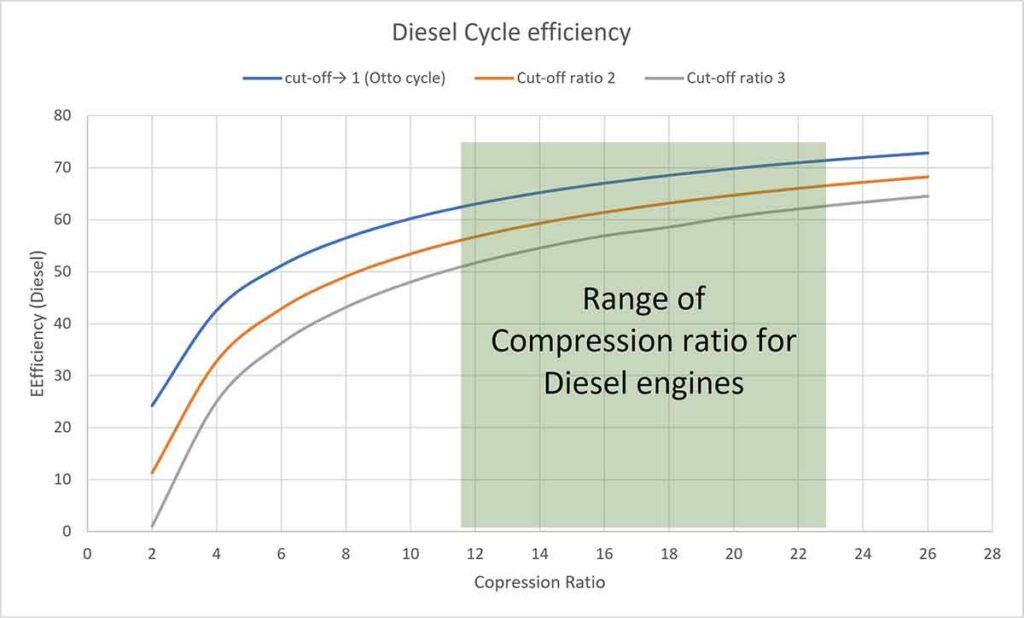
Thus, efficiency is a function of compression ratio and cut-off ratio ( γ = constant). Putting different values of rc (assuming γ = 1.4 for air), the efficiencies are tabulated below. The cut-off ratio is the measure of the duration of heat addition at constant pressure. Point 2 in the P-V diagram represents the beginning of heat addition and point 3 represents the completion of heat addition while the piston moves from TDC to BDC. In a Diesel engine, it is related to the duration of fuel injected inside the cylinder. The Diesel engines are generally constructed for a range of compression ratios from 14:1 to 22:1.
| rc | 2 | 4 | 6 | 8 | 10 | 12 | 14 | 16 | 18 | 20 | 22 | 24 | 26 |
 | 11.3 | 32.8 | 42.9 | 49 | 53.4 | 56.7 | 59.3 | 61.4 | 63.2 | 64.7 | 66 | 67.2 | 68.2 |
 | 1.1 | 25 | 36.3 | 43.2 | 48 | 51.7 | 54.6 | 56.9 | 58.6 | 60.6 | 62.1 | 63.4 | 64.5 |
From the table and the graph, you can understand that efficiency increases with an increase in compression ratio for a particular cut-off ratio. The efficiency of the Otto cycle is more than that of the Diesel cycle. But SI engine does not work on a higher compression ratio because of the limitation of pre-ignition. A Diesel engine works on a higher compression ratio. Therefore, the thermal efficiency of the Diesel engine is more than that of the Petrol Engine. As the cut-off ratio approaches 1, the cycle approaches to be an Otto cycle.
You also watch the videos on the Otto Cycle, Diesel Cycle, and Dual cycle. For numerical problem solving consider watching this video.
Brayton or Joule cycle
The approximation of a Gas turbine is Brayton Cycle which is a rotary Heat engine. The closed cycle Gas turbine is an External Combustion engine, and the open cycle gas turbine is an Internal combustion engine. In a closed-cycle Gas turbine, heat transfer takes place in constant pressure heat exchangers.
Assumptions: The working fluid is air. The specific heat remains constant.
Gas turbine: Brayton cycle Engine
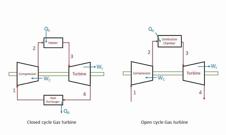
- Process 1-2: Isentropic compression in a compressor.
- Process 2-3: Constant pressure heat addition (either in a heater or in a combustion chamber).
- Process 3-4: Isentropic expansion in a Turbine.
- Process 4-1: Constant pressure heat rejection (either in a heat exchange or exhaust of burnt gases into the atmosphere.
In a closed cycle gas turbine the working fluid is reused after cooling in a heat exchanger. compressed air is heated in a heater by burning fuel externally. The hot air (working fluid is then expanded in the turbine. In an open-cycle Gas turbine fuel is burnt in a combustion chamber (heat addition) and the product of combustion is exhausted into the atmosphere after expansion in the turbine.
P-V and T-S diagram
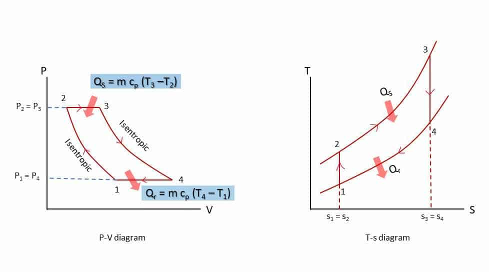
Thermal Efficiency of Brayton cycle
![\[\eta_{brayton} =\eta_{th}= \frac{W_{net}}{Q_s}\]](https://gyan4all.com/wp-content/ql-cache/quicklatex.com-2e8525a90abec94660f48add5f1f1562_l3.png "Rendered by QuickLaTeX.com")
![\[\eta_{th} = \eta_{brayton} =1- \frac{Q_{r}}{Q_s}\]](https://gyan4all.com/wp-content/ql-cache/quicklatex.com-f8c60630688def93399e5db56fab6478_l3.png "Rendered by QuickLaTeX.com")
![\[=1- \frac{mc_{p}{(T_4-T_1)}}{mc_{p}{(T_3-T_2)}}\]](https://gyan4all.com/wp-content/ql-cache/quicklatex.com-f64ccf9092a7fea9a817ce7c33c26b8c_l3.png "Rendered by QuickLaTeX.com")
![\[=1- \frac{(T_4-T_1)}{(T_3-T_2)} \rightarrow (i)\]](https://gyan4all.com/wp-content/ql-cache/quicklatex.com-3c829ed63f91521609ccefa54166faa8_l3.png "Rendered by QuickLaTeX.com")
Applying isentropic law to the process 1-2 and 3-4
![\[\frac{T_2}{T_1}= \left(\frac{{p_2}}{{p_1}}\right)^{\frac{\gamma-1}{\gamma}\]](https://gyan4all.com/wp-content/ql-cache/quicklatex.com-af341686408c2bdbc8a26a332a93fdf2_l3.png "Rendered by QuickLaTeX.com")
Therefore,
![\[T_2= T_1{r_p}^\left({\frac{\gamma-1}{\gamma}\right)\]](https://gyan4all.com/wp-content/ql-cache/quicklatex.com-e0ce07e1d5a4ad91cccf577838ec1c0e_l3.png "Rendered by QuickLaTeX.com")
Where, rp = Pressure ratio =
![\[\frac{P_2}{P_1} = \frac{P_3}{P_4}\]](https://gyan4all.com/wp-content/ql-cache/quicklatex.com-0d3293d8c5f9efeaa12c3123b8616edc_l3.png "Rendered by QuickLaTeX.com")
![\[Since, P_1 = P_4, and, P_2 = P_3\]](https://gyan4all.com/wp-content/ql-cache/quicklatex.com-db0ae698963941a887de368372ae607f_l3.png "Rendered by QuickLaTeX.com")
and
![\[\frac{T_3}{T_4}= \left(\frac{{p_3}}{{p_4}}\right)^{\frac{\gamma-1}{\gamma}\]](https://gyan4all.com/wp-content/ql-cache/quicklatex.com-23274c3ab3be8746d52faa30cb85014a_l3.png "Rendered by QuickLaTeX.com")
![\[\frac{T_3}{T_4}= \left(\frac{{p_2}}{{p_1}}\right)^{\frac{\gamma-1}{\gamma}\]](https://gyan4all.com/wp-content/ql-cache/quicklatex.com-047adeb843b10a56c07f503740889d59_l3.png "Rendered by QuickLaTeX.com")
Therefore,
![\[T_3= T_4{r_p}^\left({\frac{\gamma-1}{\gamma}\right)\]](https://gyan4all.com/wp-content/ql-cache/quicklatex.com-9adcc2ad1ad648f912b5b7d157a84b4d_l3.png "Rendered by QuickLaTeX.com")
Putting the values of T2 and T3 in equation (i),
![\[\eta_{th} = 1- \frac{T_1}{T_2}\]](https://gyan4all.com/wp-content/ql-cache/quicklatex.com-f81ff24e97a932debae1d643566c5a2a_l3.png "Rendered by QuickLaTeX.com")
![\[= 1-\left(\frac{P_1}{P_2}\right)^\frac{\gamma-1}{\gamma}\]](https://gyan4all.com/wp-content/ql-cache/quicklatex.com-6f9b0c8ff9b022fb34d127a6aae685bd_l3.png "Rendered by QuickLaTeX.com")
![\[= 1-\left(\frac{1}{r_p}\right)^\frac{\gamma-1}{\gamma}\]](https://gyan4all.com/wp-content/ql-cache/quicklatex.com-35f8252a62419a55687e562ae44879b5_l3.png "Rendered by QuickLaTeX.com")
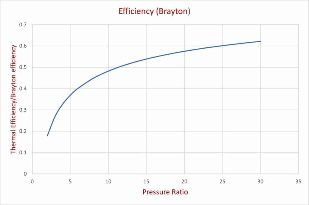
Thus, efficiency of gas turbineis a function of pressure ratio(rp).
Putting different values of rp we can get the respective values of thermal efficiencies of the gas turbine. The tabulated values and the corresponding graph are shown below:
| rp | 2 | 4 | 6 | 8 | 10 | 12 | 14 | 16 | 18 | 20 | 22 | 24 | 26 |
| .18 | .33 | .4 | .45 | .48 | .51 | .53 | .55 | .56 | .58 | .59 | .59 | .61 |
At a higher pressure ratio, the highest temperature of the gas will be too high. At higher temperatures, the turbine material may not withstand the high pressure of the gas because of the effect of temperature on mechanical properties. Special heat resistant material has to be chosen for high temperature and pressure of gas turbine.
Otto cycle has two isentropic processes and two constant volume processes.
Diesel cycle processes are Isentropic compression, Constant pressure heat addition, Isentropic expansion, and Constant volume heat rejection.
The thermal efficiency of the Petrol engine (Otto cycle) is a function of the Compression ratio. So Thermal efficiency of the petrol engine increases if the compression ratio increases.
Although the efficiency of the otto cycle is more than the efficiency of the Diesel cycle, the Petrol engine has the limitation of compression ratio. At a higher compression ratio (more than 11), knocking takes place due to preignition. Therefore Petrol engine works in the range of compression ratio of 7 to 11. Whereas, the Diesel engine works at a higher compression ratio (14 to 22) and has higher efficiency than that of a Petrol engine.
In the Otto cycle, heat transfer (addition and rejection) takes place at constant volume while in a Joule cycle, heat interactions take place at constant pressure.
The air standard efficiency of the Otto cycle is a function of compression ratio while the air standard efficiency of the Brayton or Joule cycle depends on the Pressure ratio.
In the Otto cycle heat addition takes place at constant volume while in a Diesel cycle, heat addition takes place at constant pressure. The Otto cycle is an approximation of SI engine (Petrol engine) and the Diesel cycle is an approximation of CI (Diesel) engine.